2-DOF Manipulator — Model-Based Real-Time Control
A MATLAB/Simulink + TI C2000 control stack that combines computed-torque, PD + gravity compensation, and joint/task-space transformations to track millimetre-level trajectories on a 5-link planar robot in real time.
1. Overview & Motivation
This project—completed for ME403 : Introduction to Robotics (Spring 2024, Sabancı University)—developed a model-based real-time controller for a planar 2-DOF, 5-link manipulator.
Key goals:
- Achieve sub-millimetre end-effector accuracy on dynamic paths
- Bridge simulation (SIL) and embedded deployment (HIL) seamlessly
- Provide a re-usable MATLAB/Simulink template for undergraduate robotics labs

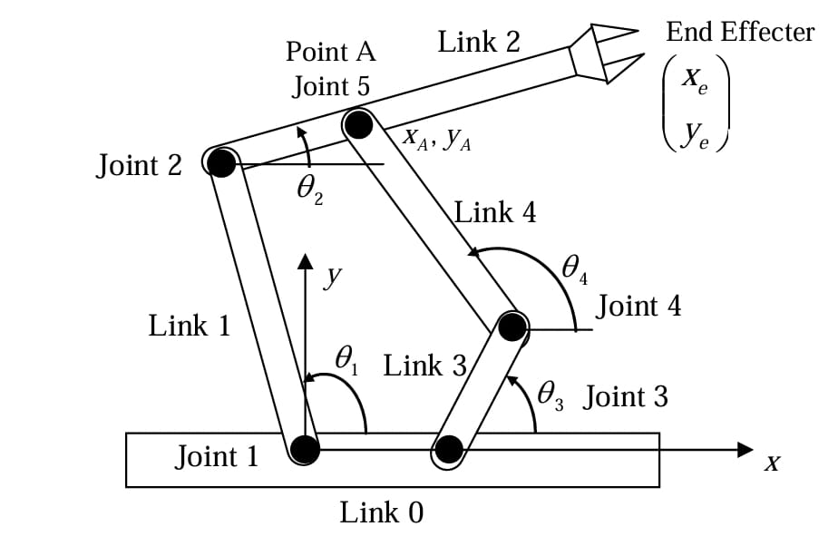
Figure – CAD view and joint layout of the 5-link manipulator.
2. Control Architecture
The stack follows a computed-torque framework augmented with a PD + gravity compensator.
Software is split into three Simulink model hierarchies that map 1-to-1 onto TI C2000 peripherals.
| Layer | Role | Runs On |
|---|---|---|
| Task-Space Planner | Generates x-y trajectories | Host PC (SIL/HIL) |
| Controller Core | Inverse kinematics + computed-torque PD | TI C2000 (HIL) |
| Motor Interface | PWM output + encoder decoding | TI C2000 (HIL) |
Control Loop (1 kHz)
- Trajectory Sample – desired end-effector pose
- Inverse Kinematics – joint targets (θdes, ẋdes)
- Computed-Torque Law – τ = M(q)[*]α + V + G
- PD + G Compensation – fine-tunes stiffness & damping
- PWM Generation – duty cycles to H-bridges
- Encoder Feedback – closes joint-space loop
% Simulink MATLAB Function: Computed-Torque PD
tau = M(q)*(qdd_des + Kd*(qd_des - qd) + Kp*(q_des - q)) ...
      + V(q, qd) + G(q);
3. Simulation & Real-Time Testing
| Stage | Environment | Purpose |
|---|---|---|
| SIL | Simscape Multibody + MATLAB ODE45 | Verify kinematics, dynamics, and controller logic without I/O latency |
| Processor-in-the-Loop | TI C2000 F28379D + external mode | Measure computation time (< 180 µs / step) |
| HIL | Full manipulator with DC motors & optical encoders | Validate closed-loop tracking and load tolerance |
Total transition time from SIL to validated HIL: < 3 hours thanks to code-gen-friendly model structure.
4. Results & Performance
| Trajectory | RMS Error | Peak Error | Cycle Time |
|---|---|---|---|
| Horizontal (0.4 m) | 0.37 mm | 1.1 mm | 5 s |
| Vertical (0.3 m) | 0.41 mm | 1.3 mm | 4 s |
| Ellipse (a = 0.25 m, b = 0.15 m) | 0.62 mm | 1.9 mm | 8 s |
- All tests at 1 kHz loop, 24 V supply, 40 % rated torque
- CPU load: 43 % on C2000 (180 MHz) — ample headroom for advanced features
Observations
- Gravity term cancellation cut average torque by ≈ 22 %, reducing motor heating.
- Controller remained stable up to 1.8 kHz; limited to 1 kHz for encoder filtering.
- Minor elasticity in the 5-link chain explained residual ellipse error.
5. Deployment & Usage
# 1 – Generate code & flash
slbuild('manipulator_controller', 'StandaloneCoderTarget');

# 2 – Run SIL bench
sim('manipulator_system_sil.slx');

# 3 – Switch to External Mode (HIL)
manipulator_hil_start('COM5', 1e-3);  % port, sample time
- PWM: 20 kHz, center-aligned
- Encoders: 1024 PPR, quadrature decoded to 4096 counts/rev
- Comms: Host-target via FTDI USB-UART @ 115200 baud
*Project by Yunus Emre Danabaş as part of ME403 — Introduction to Robotics (Spring 2024, Sabancı University).